WATER INRUSH BLOCKING TECHNOLOGY FOR TUNNEL ACCESS SHAFT SIDEWALL
Method to stop water inrush in shaft excavation.
1. Project Background
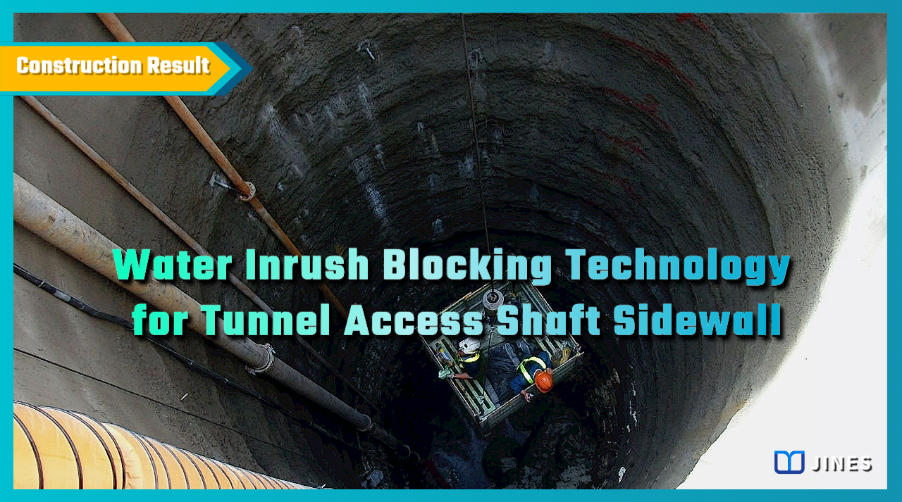
Water Inrush : When a drainage tunnel was being excavated near the bottom of an access shaft, an inrush of high-pressure fissure water was encountered at the rock formation/fracture zone joint plane.
The water output was more than 3.0m3 per minute, causing serious flooding of the shaft and gradual destruction of the shotcrete shaft wall, and there was a risk of sidewall collapse.In order to find an appropriate solution, the contractor urgently convened local tunnel experts to jointly develop a solution.


―
2. Solution
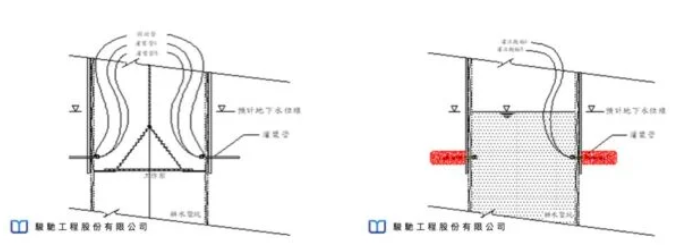
After careful research and analysis by experts from various units, it was decided to use the water pressure balance technology with long-acting micro-expansion PU resin (TIPOR-02) grouting.
First create non-high-pressure water inrush conditions in the shaft, and then carry out the horizontal rock (soil) layer leakage-stop grouting, establish a water-stop curtain to block the inrush water from the rock fissures, while stabilizing the surrounding fractured rock layers.

―
3. Works Design
The main purpose of this grouting project is to block the water inrush into the drainage tunnel shaft excavation. The construction process planning is carried out in 3 stages, namely:
(1) Block the strata that may continue water inrush besides the main gushing path.
(2) Water stop and block off the main inrush route.
(3) Depending on the results of the plugging, the leaking areas will be supplemented with grouting.
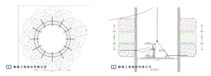
The drilling and grouting design is to arrange 12 holes around the circumference of each section; drilling depth of 2.0m; the drilling angle is vertical to the shaft; the interval between each group of sections is 1.5m; the drilling and grouting range is from the upper edge of the highest groundwater level to the bottom of the shaft.

―
4. Works Process
Since the depth of the shaft for water inrush blocking is about 30m, the working platform cannot be erected due to serious water inrush inside.
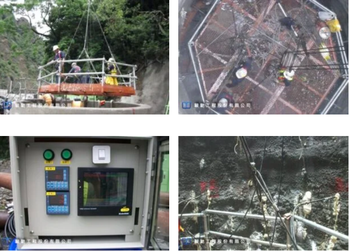
The process of drilling and installing the grouting pipeline uses a suspended octagonal gondola with adjustable side supports as a work platform to obtain sufficient stability and convenience.
Execution steps, “drilling → embedding → installing water stop → drilling and blocking → LW filling → water injection → PU grouting” and other processes, and with “drilling odd holes first” → “grout odd holes” → “and then “drill even-numbered holes “→” grout even-numbered holes” as the principle. Use flow and pressure automatic control equipment for injection.

―
5. Results
Because of the complex stratum conditions surrounding the shaft, the water inrush was only partially reduced after the completion of the first and second stages of grouting.
However, the main water outflow area was fully understood during that process, and the possible continuous water inrush path around the shaft was fully blocked. The main water inrush area was drilled and grouted through the third stage; the drill hole was deepened to 3.5m according to the rock fracture range.
After increasing the average injection volume to 400l/hole, the water inrush rate was reduced to less than 0.33m3 per minute, which completely eliminated the shaft bottom pump and was suitable for concrete pouring of the shaft lining. Water inrush control in the access shaft in this complex stratum tunnel job was smoothly achieved.

―
・More Construction Result Sharing
Contact us:+886 2769-2355
TBM Shaft Horizontal Grouting Site Improvement Technology
將下載檔案寄至:
Copyright ©Jines Construction Co.,Ltd